Question 9
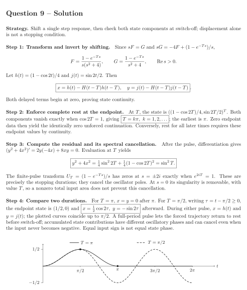
A rectangular input drives an initially resting oscillator: Use the causal step convention for . States are continuous at , and equations at the switch are understood one-sidedly.
Tasks
Find both Laplace transforms and express the response as an undelayed step response minus its delayed copy.
Calculate and determine exactly which positive pulse durations leave the state at rest forever after the pulse ends.
For arbitrary , calculate the constant value of after switch-off. Relate complete cancellation to zeros of the input transform at the oscillator poles.
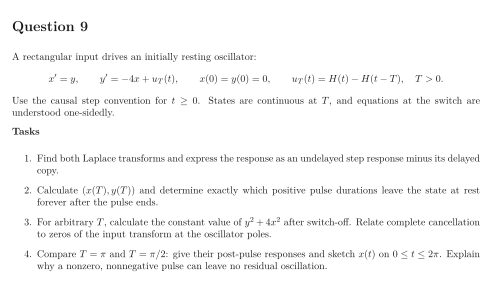
Compare and : give their post-pulse responses and sketch on . Explain why a nonzero, nonnegative pulse can leave no residual oscillation.
Show solutionHide solution
Question 9 – Solution
Strategy. Shift a single step response, then check both state components at switch-off; displacement alone is not a stopping condition.
Step 1: Transform and invert by shifting. Since and , Let and . Then Both delayed terms begin at zero, proving state continuity.
Step 2: Enforce complete rest at the endpoint. At , the state is . Both components vanish exactly when , giving ; the earliest is . Zero endpoint data then yield the identically zero unforced continuation. Conversely, rest for all later times requires these endpoint values by continuity.
Step 3: Compute the residual and its spectral cancellation. After the pulse, differentiation gives . Evaluation at yields The finite-pulse transform has zeros at exactly when . These are precisely the stopping durations; they cancel the oscillator poles. At its singularity is removable, with value , so a nonzero total input area does not prevent this cancellation.
Step 4: Compare two durations. For , after . For , writing , the endpoint state is and afterward. During either pulse, and ; the plotted curves coincide up to . A full-period pulse lets the forced trajectory return to rest before switch-off; accumulated state contributions have different oscillatory phases and can cancel even when the input never becomes negative. Equal input sign is not equal state phase.
See the diagram in the original worksheet below.