Question 3
A delayed input drives the zero-state system Here is zero for and one for ; its value at the switch does not affect the continuous state. Interpret derivatives there one-sidedly.
Tasks
Find the transforms of both components and identify the factor that encodes the input delay.
Invert them to obtain a piecewise solution. Explain why multiplying an undelayed response by does not implement a delay.
Determine continuity of at , and find the one-sided values of there.
Prove both components increase after the switch and approach their limits without overshoot. Sketch their time responses, marking the switch and limiting levels.
Show solutionHide solution
Question 3 – Solution
Strategy. First invert the undelayed rational factors, then translate the entire response using the second shifting theorem.
Step 1: Transform both equations. With and , and . Hence It is , rather than an exponential in time, that encodes the delay.
Step 2: Shift the inverse transforms. The undelayed inverses are and . Writing , the solution is zero for , and for , These formulas give zero at the joining point. Multiplication by would change decay rates while generally leaving a nonzero response before ; it is a different transform operation.
Step 3: Check the switch regularity. Both states are continuous. Before the switch their derivatives vanish; after it and . Thus , , whereas . Afterward , so . In particular is continuously differentiable at the switch but is not twice differentiable there.
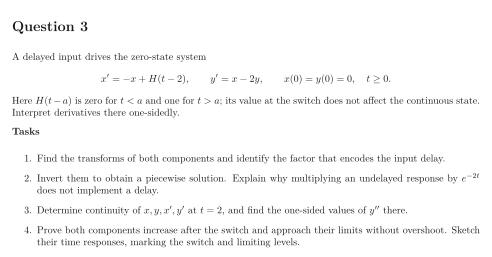
Step 4: Establish shape and limits. For , and . Also and , with limits and . These inequalities prove the absence of overshoot for all later times. The dotted horizontal guides in the sketch are limits; the solid and dashed curves are the components. Both remain zero throughout the waiting interval.
See the diagram in the original worksheet below.