Question 5
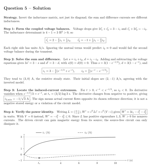
Two magnetically coupled loops have inductances H, mutual inductance H, and resistances . Reference current directions and coil orientations are chosen so the mutual derivative terms have positive signs in both voltage-drop balances. At a constant V source is connected to loop 1; loop 2 has no source. Initially both currents are zero. Time is in seconds; the ideal linear circuit model applies.
Tasks
Use Kirchhoff’s voltage law to derive the coupled derivative equations, then solve them for . Explain why the inductance matrix is invertible.
Solve the initial-value problem using current sum and difference, and find the limiting currents.
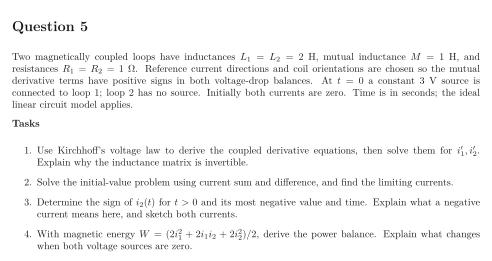
Determine the sign of for and its most negative value and time. Explain what a negative current means here, and sketch both currents.
With magnetic energy , derive the power balance. Explain what changes when both voltage sources are zero.
Show solutionHide solution
Question 5 – Solution
Strategy. Invert the inductance matrix, not just its diagonal; the sum and difference currents see different inductances.
Step 1: Form the coupled voltage balances. Voltage drops give and . The inductance determinant is H, so Each right side has units A/s. Ignoring the mutual terms would predict and would fail the second voltage balance during the transient.
Step 2: Solve the sum and difference. Let , . Adding and subtracting the voltage equations gives and , with . Thus , , and They tend to A, the resistive steady state. Their initial slopes are A/s, agreeing with the inverted model.
Step 3: Locate the induced-current extremum. For , , so . Its derivative vanishes when , at s. The derivative changes from negative to positive, giving . The sign means actual current flows opposite its chosen reference direction; it is not a negative stored energy or a violation of the circuit model.
Step 4: Verify the power identity. Writing , gives in watts. With instead, . Since has positive eigenvalues , for nonzero currents. The driven circuit can gain magnetic energy from its source; the source-free circuit can only dissipate it.
See the diagram in the original worksheet below.